
Skip to content
CodesErreur.comSWISS PRO ENGINE
Core Diagnostics
DiagnosticsBrandsOEM ManualsSpecialistsAI EngineerPRO
Workshop Tools
Diagnostic ToolsNEW
Hardware interfaces & test probes
Find Rating Plate
Locate exact E-Nr, PNC & serial codes
Parts Locator
Global OEM spare parts suppliers
Community & Career
Academy & Courses
Masterclasses by senior technicians
Certification ExamsPRO
Verify your B2B technical credentials
Elite Forum
Peer-to-peer field troubleshooting
Tech Jobs
B2B recruitment & field opportunities
Leaderboard
Global ranking of verified specialists
Certified Appliance Engineering EcosystemApply for Certification →
Language Selector
Account & Access
Upgrade PRO
Back to Search
OEM VERIFIED BENCH
OFFICIAL FAULT CODEEr04
Hoover
Hoover // OFFICIAL DIAGNOSTIC BENCH

Hoover Er04

OvenDrive Motor, Inverter & Tachometer Sensor
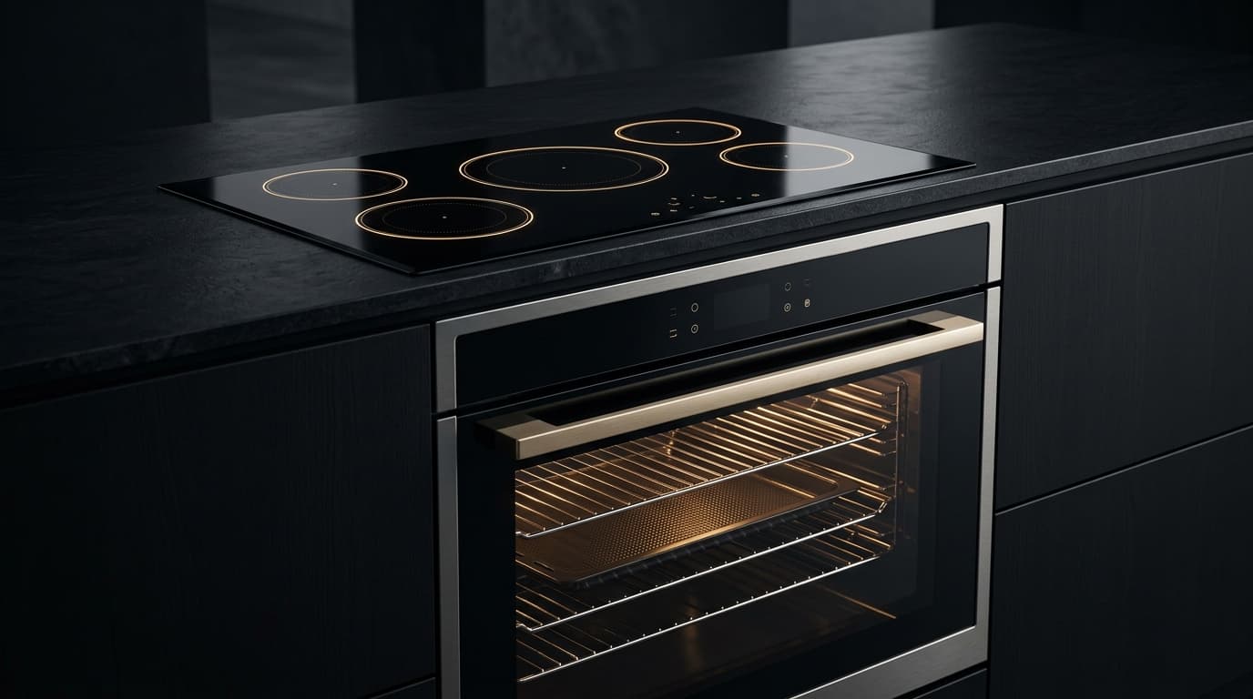
Integrated luxury convection oven and induction cooktop with illuminated touch controls
Oven
Other Brands Sharing Code Er04:HaierER04CandyER04BrandtER04De DietrichER04FAGORER04RosieresER04SauterER04GEER04IbernaER04ZerowattER04

Symptom / Description

FAULT

Hoover H-OVEN 300 / 500 / 700 Steam & Pyrolytic Smart Oven: Tangential cooling fan failure Er04; electronics cooling blower tachometer signal absent or speed falls below minimum RPM.

TELEMETRY // LIVESIG: FAULT_DETECTED

Root Cause

ROOT CAUSE

On Hoover ovens utilizing H-OVEN Steam & Pyrolytic convection system, multi-point electronic heat management, and hOn digital intelligence: Jammed cross-flow fan impeller, open fan motor winding (~180–350 Ω), or defective Hall effect tachometer sensor.

CIRCUIT // SUBSYSTEMLOGIC: ROOT_ISOLATED

Repair Instructions

UNLOCKED
1Inspect tangential fan above cavity for free spin. Measure fan motor coil resistance (~180–350 Ω across terminals). Check Hall sensor 5V DC supply. Turn oven control to Off, isolate at main distribution board for 90 seconds, restore power and touch Timer icon for 3 seconds.
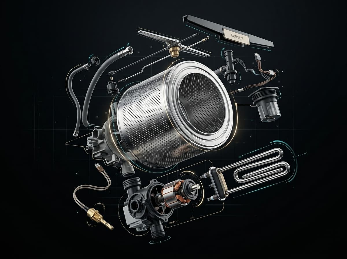
AI diagnostic workshop engine analyzing appliance circuit schematics and error telemetry in real time
AI WORKSHOP PROTOCOL ENGINE
Direct extraction from OEM factory manuals & wiring schematics

Field Actions

DISPATCH
Need Help? Call a Certified TechnicianWorldwide Hoover Parts Finder
Electrical & Safety Protocol

Always disconnect appliance from 230V/400V mains before opening panels. Use CAT III multimeter for circuit testing.
CALIBRATED BENCH PROTOCOL // CAT III 600V

Workshop Verification & Safety Checklist

WORKSHOP VERIFICATION PROTOCOLDrive Motor, Inverter & Tachometer SensorOven / Microwave
2. Multimeter & Electrical Bench Tests (Ω)
MODE: OHMMETER (Ω)AUTO-RANGE
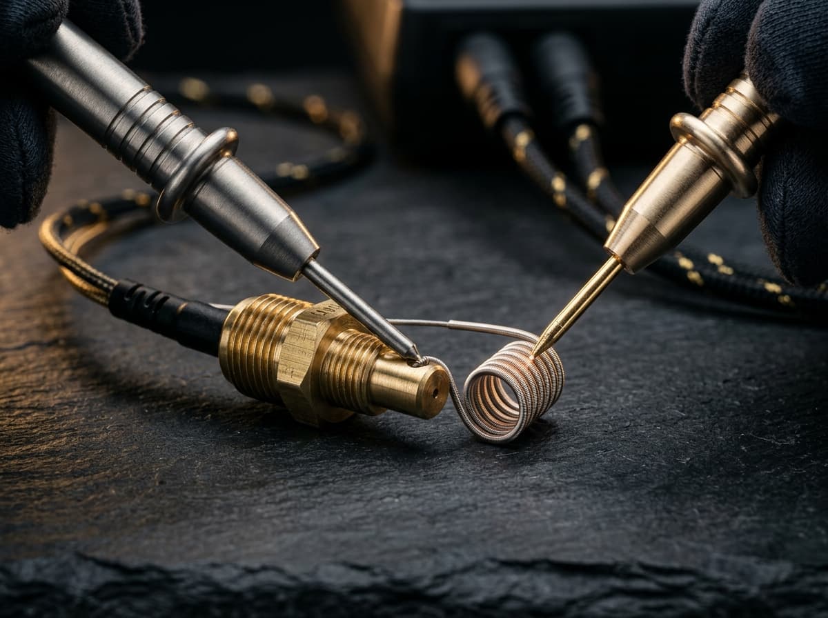
Precision digital multimeter probes measuring electrical resistance in Ohms on an appliance control board
CALIBRATED METROLOGY RESISTANCE BENCH (CAT III)
Nominal Resistance (Ω)
3Ω–6Ω (BLDC phase U-V-W) / 60Ω–180Ω (Tacho coil) / 1.5Ω–3.5Ω (Universal stator)NOMINAL
0 Ω (SHORT)CALIBRATED BAND∞ OL (OPEN)
▲ NOMINAL OPERATING WINDOW
Target Component:3-Phase Motor Windings / Tacho Generator / Carbon Brushes
Test Pins & Connections
PROBE (+)
PROBE (-)
Across phase pins U-V, V-W, U-W on motor harness; across tacho pins
Tolerance & Diagnostic CriteriaBLDC phase winding values must be strictly balanced within ±0.3Ω. Hand rotation generates 1V–4V AC on tacho.
1. Pre-Intervention Electrical Safety Protocols
  • !High-Voltage Safety Protocol & DC Bus: Wait at least 5 minutes after power cutoff to allow inverter DC bus capacitors (380V DC) to bleed down.
  • !Verify 0V DC across inverter filter capacitors before unplugging motor harness connectors.
  • !Keep hands clear of drive belt and pulleys during any manual rotation tng.
3. Preliminary Mechanical & Visual Checks
  • Slip off drive belt and spin drum/motor shaft by hand to check for roaring or seized ball bearings.
  • For universal motors: verify carbon brushes have at least 10mm remaining length and smooth contact faces.
  • Inspect motor suspension rubber mounts and drive belt tension/groove profile.
Perform these diagnostic steps before triggering AI Deep Search or replacing boards.Certified Workshop Routine

Frequently Asked Questions: Hoover ER04

FAQ TREE
What does error code ER04 mean on a Hoover appliance?

Hoover error code ER04 indicates: Hoover H-OVEN 300 / 500 / 700 Steam & Pyrolytic Smart Oven: Tangential cooling fan failure Er04; electronics cooling blower tachometer signal absent or speed falls below minimum RPM..

What is the root cause of Hoover error code ER04?

The primary root cause for Hoover code ER04 is: On Hoover ovens utilizing H-OVEN Steam & Pyrolytic convection system, multi-point electronic heat management, and hOn digital intelligence: Jammed cross-flow fan impeller, open fan motor winding (~180–350 Ω), or defective Hall effect tachometer sensor..

How do I fix or resolve Hoover error code ER04?

To resolve error code ER04: Inspect tangential fan above cavity for free spin. Measure fan motor coil resistance (~180–350 Ω across terminals). Check Hall sensor 5V DC supply. Turn oven control to Off, isolate at main distribution board for 90 seconds, restore power and touch Timer icon for 3 seconds.

Is it safe to clear Hoover error code ER04 by resetting power?

Resetting power (unplugging for 5–10 minutes) clears temporary memory errors. However, if Hoover code ER04 persists, the physical component causing On Hoover ovens utilizing H-OVEN Steam & Pyrolytic convection system, multi-point electronic heat management, and hOn digital intelligence: Jammed cross-flow fan impeller, open fan motor winding (~180–350 Ω), or defective Hall effect tachometer sensor. must be inspected or replaced.

How do I test electrical resistance for Hoover code ER04 using a multimeter?

Set a digital multimeter to ohms (Ω). Disconnect power and test 3-Phase Motor Windings / Tacho Generator / Carbon Brushes across Across phase pins U-V, V-W, U-W on motor harness; across tacho pins. Expected nominal reading is 3Ω–6Ω (BLDC phase U-V-W) / 60Ω–180Ω (Tacho coil) / 1.5Ω–3.5Ω (Universal stator). Tolerance: BLDC phase winding values must be strictly balanced within ±0.3Ω. Hand rotation generates 1V–4V AC on tacho..

What safety protocol must be followed before servicing Hoover code ER04?

Standard electrical safety protocol: 1. Disconnect 230V mains power before opening panels. 2. Verify zero voltage at test points. 3. Allow hot water or heating elements to cool below 30°C before handling.

Community Verification

COMMUNITY

Did this solution resolve the issue?

SEMANTIC KNOWLEDGE GRAPH // HOOVER

Related Hoover Oven / Microwave Error Codes

Diagnostic Link Mesh14 OEM Cross-References

Cross-referenced diagnostic codes for technicians inspecting similar component subsystems.

Er05Drive Motor, Inverter & Tachometer Sensor
Hoover H-OVEN 300 / 500 / 700 Steam & Pyrolytic Smart Oven: Pyrolysis door lock latch failur...
Inspect Protocol
Er06Drive Motor, Inverter & Tachometer Sensor
Hoover H-OVEN 300 / 500 / 700 Steam & Pyrolytic Smart Oven: Pyrolysis door unlock timeout Er...
Inspect Protocol
Er07NTC Temperature Sensor & Thermistor
Hoover H-OVEN 300 / 500 / 700 Steam & Pyrolytic Smart Oven: Food meat probe circuit fault Er...
Inspect Protocol
Er08Heating Element, Thermostat & Safety Fuse
Hoover H-OVEN 300 / 500 / 700 Steam & Pyrolytic Smart Oven: Power relay board communication ...
Inspect Protocol
Er09Water Level Pressure Switch & Air Dome
Hoover H-OVEN 300 / 500 / 700 Steam & Pyrolytic Smart Oven: Stuck touch control key error Er...
Inspect Protocol
Er15NTC Temperature Sensor & Thermistor
Hoover H-OVEN 300 / 500 / 700 Steam & Pyrolytic Smart Oven: Electronics housing ambient over...
Inspect Protocol
Er20Electronic Control Board (PCB) & Bus Communications
Hoover H-OVEN 300 / 500 / 700 Steam & Pyrolytic Smart Oven: Microcontroller flash memory che...
Inspect Protocol
Er21Electronic Control Board (PCB) & Bus Communications
Hoover H-OVEN 300 / 500 / 700 Steam & Pyrolytic Smart Oven: Low-voltage DC power supply ripp...
Inspect Protocol
Er22Electronic Control Board (PCB) & Bus Communications
Hoover H-OVEN 300 / 500 / 700 Steam & Pyrolytic Smart Oven: Touch control panel matrix evalu...
Inspect Protocol
Er31Electronic Control Board (PCB) & Bus Communications
Hoover H-OVEN 300 / 500 / 700 Steam & Pyrolytic Smart Oven: Appliance variant model configur...
Inspect Protocol
Er36NTC Temperature Sensor & Thermistor
Hoover H-OVEN 300 / 500 / 700 Steam & Pyrolytic Smart Oven: Display console temperature sens...
Inspect Protocol
Er47Heating Element, Thermostat & Safety Fuse
Hoover H-OVEN 300 / 500 / 700 Steam & Pyrolytic Smart Oven: LIN-bus communication error Er47...
Inspect Protocol
Er56Electronic Control Board (PCB) & Bus Communications
Hoover H-OVEN 300 / 500 / 700 Steam & Pyrolytic Smart Oven: Analog-to-digital converter refe...
Inspect Protocol
F0Electronic Control Board (PCB) & Bus Communications
Hoover H-OVEN 300 / 500 / 700 Steam & Pyrolytic Smart Oven: User interface board communicati...
Inspect Protocol
CodesErreur.com

Premium appliance diagnostics & repair database.
Powered by AI to help certified technicians worldwide.

Trusted by professionals in CH & FR

Platform

Search DatabasePRO Diagnostic AIPRODiagnostic ToolsBrands

Workshop Tools

Brands (87)OEM ManualsFind Rating PlateParts Locator

For Technicians

SpecialistsTechnician ForumTech JobsPremium

Corporate

Terms of ServicePrivacy PolicyOfficial Swiss Repair Partner: Electroassistance
OPERATIONAL SAFETY SPECIFICATION

SAFETY DISCLAIMER

The technical information, diagnostic guides, error codes, and AI-generated suggestions provided on this website are intended exclusively for certified and qualified professionals. Appliance repair involves severe electrical hazards, high voltages, and mechanical risks that can result in fatal injury or severe property damage. If you are not a trained technician, do not attempt to repair any appliances. CodesErreur assumes no responsibility or liability for any damage, injury, or consequential losses resulting from the use of the information provided on this platform. You use all information entirely at your own risk.

© 2026 CodesErreur. All rights reserved.

Official Swiss Repair Partner: Electroassistance Terms of Service Privacy Policy