
Skip to content
CodesErreur.comSWISS PRO ENGINE
Core Diagnostics
DiagnosticsBrandsOEM ManualsSpecialistsAI EngineerPRO
Workshop Tools
Diagnostic ToolsNEW
Hardware interfaces & test probes
Find Rating Plate
Locate exact E-Nr, PNC & serial codes
Parts Locator
Global OEM spare parts suppliers
Community & Career
Academy & Courses
Masterclasses by senior technicians
Certification ExamsPRO
Verify your B2B technical credentials
Elite Forum
Peer-to-peer field troubleshooting
Tech Jobs
B2B recruitment & field opportunities
Leaderboard
Global ranking of verified specialists
Certified Appliance Engineering EcosystemApply for Certification →
Language Selector
ENFRDEITESPT
ENEnglishFRFrançaisDEDeutschITItalianoESEspañolPTPortuguês
Account & Access
Upgrade PRO
Back to Search
OEM VERIFIED BENCH
OFFICIAL FAULT CODEF0
Hoover
Hoover // OFFICIAL DIAGNOSTIC BENCH

Hoover Hob F0

HobNTC Temperature Sensor & Thermistor
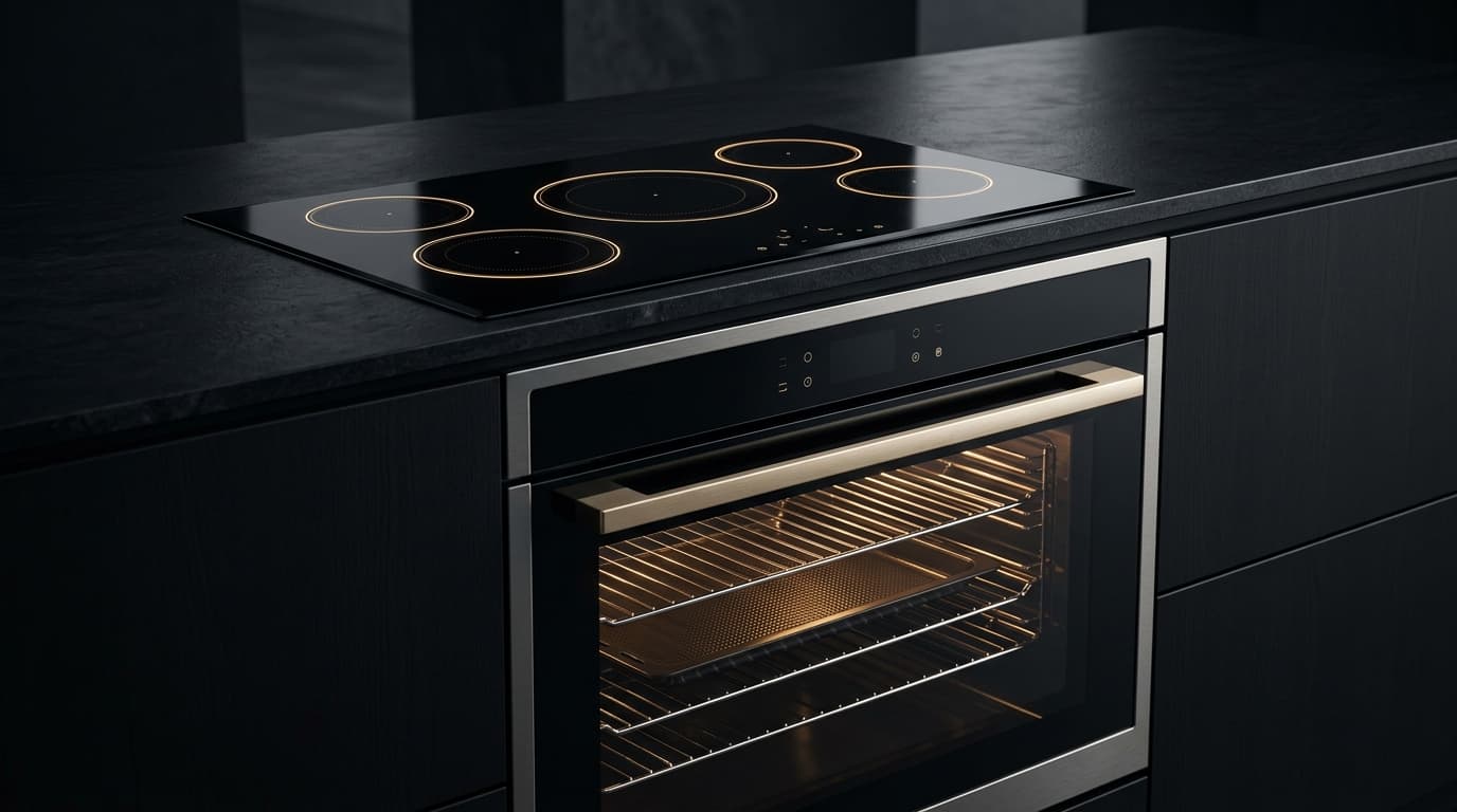
Integrated luxury convection oven and induction cooktop with illuminated touch controls
Hob
Select Appliance Type
0ms Instant Telemetry Switch
Haier / Candy / Hoover / GE Group: Equivalent Code Across OEM Group Brands
Haier Europe / Candy-Hoover Shared Electronic Platform
HaierF0CandyF0RosièresF0ZerowattF0IbernaF0GEF0
Other Brands Sharing Code F0:BoschF0MieleF0SiemensF0LGF0NeffF0BrandtF0De DietrichF0LiebherrF0

Symptom / Description

FAULT

Hoover H-HOB Induction & Multi-Zone Flex Cooktop: Cooking coil temperature sensor disconnected F0; generator board detects open circuit on temperature feedback line.

TELEMETRY // LIVESIG: FAULT_DETECTED

Root Cause

ROOT CAUSE

On Hoover cooktops utilizing H-HOB multi-zone induction power generator, IGBT inverter thermal protection, and digital touch slider control: Disconnected 2-pin spade connector on coil center thermistor, wire severed by internal metal bracket, or failed NTC.

CIRCUIT // SUBSYSTEMLOGIC: ROOT_ISOLATED

Repair Instructions

UNLOCKED
1Disconnect mains. Open glass surface. Verify 2-pin sensor plug is seated firmly in power module socket. Measure resistance (~100 kΩ at 25°C). Clear cookware off the ceramic plate, turn off breaker for 45 seconds, reconnect power and press Key Lock sensor for 6 seconds.
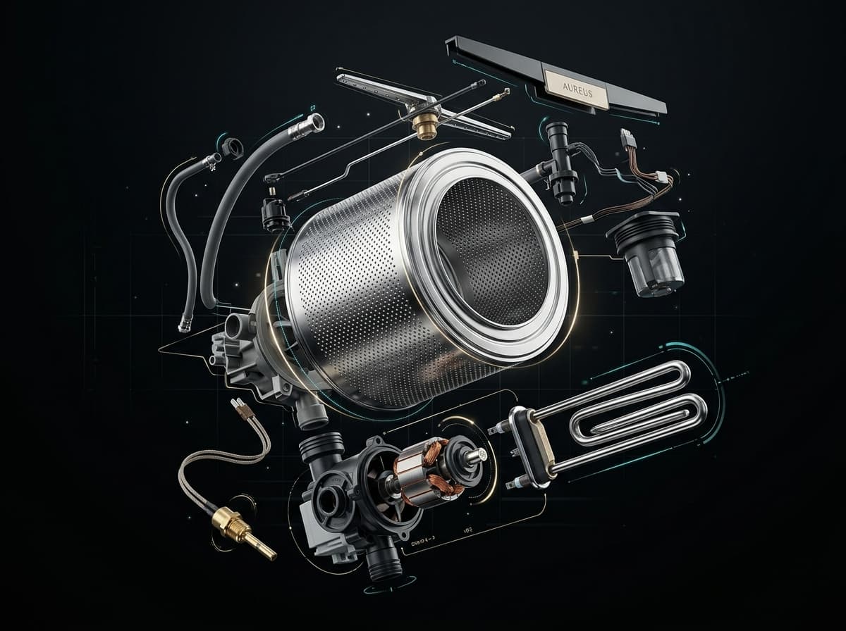
AI diagnostic workshop engine analyzing appliance circuit schematics and error telemetry in real time
AI WORKSHOP PROTOCOL ENGINE
Direct extraction from OEM factory manuals & wiring schematics

Field Actions

DISPATCH
Need Help? Call a Certified TechnicianWorldwide Hoover Parts Finder
Electrical & Safety Protocol

Always disconnect appliance from 230V/400V mains before opening panels. Use CAT III multimeter for circuit testing.

SWISS ATELIER TECHNICAL BLUEPRINT // 2026 SCHEMATIC STANDARD

Thermal & Heating Loop

Calrod Heating Element R1, Safety Klixon & NTC Thermistor Probe

CALIBRATED TEST POINTS (TP1 / TP2)
ACTIVE MULTIMETER BENCH
MAIN PCB CONTROLLER32-BIT MCUFIRMWARE v26.4SOLID-STATE RELAYTRIAC TY1 // 16A 600V230V AC MAINSLINE FILTER L-NJ1J2TP1TP2PRECISION BENCH METERAUTO-RANGE ΩCAT III24.6 ΩVΩCOMHEATING ELEMENT R1HEATER R1: 20-28 ΩSAFETY THERMOSTAT (KLIXON)NTC SENSOR (4.8-12kΩ)
Target Component
NTC Temperature Sensor Probe (Thermistor)
Nominal Resistance / Test Range
4.8kΩ–12kΩ (at 20°C–25°C)
Test Harness Pins
Across sensor pins 1-2 (unplugged harness)
Diagnostic Verification Rule
Zero or OL indicates open heating element or tripped safety thermostat. Check insulation to earth.
CALIBRATED BENCH PROTOCOL // CAT III 600V

Workshop Verification & Safety Checklist

WORKSHOP VERIFICATION PROTOCOLNTC Temperature Sensor & ThermistorHob / Cooktop
2. Multimeter & Electrical Bench Tests (Ω)
MODE: OHMMETER (Ω)AUTO-RANGE
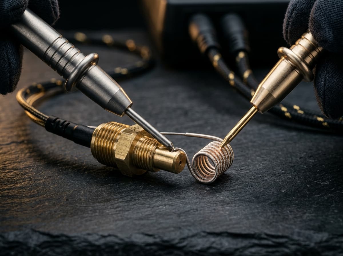
Precision digital multimeter probes measuring electrical resistance in Ohms on an appliance control board
CALIBRATED METROLOGY RESISTANCE BENCH (CAT III)
Nominal Resistance (Ω)
4.8kΩ–12kΩ (at 20°C–25°C)NOMINAL
0 Ω (SHORT)CALIBRATED BAND∞ OL (OPEN)
▲ NOMINAL OPERATING WINDOW
Target Component:NTC Temperature Sensor Probe (Thermistor)
Test Pins & Connections
PROBE (+)
PROBE (-)
Across sensor pins 1-2 (unplugged harness)
Tolerance & Diagnostic CriteriaNegative temperature coefficient: resistance drops smoothly when warmed with fingers. OL = open circuit.
1. Pre-Intervention Electrical Safety Protocols
  • !Electrical Safety Protocol: Disconnect 230V electrical mains power before removing appliance side or rear panels.
  • !Ensure tub water or heating chamber has cooled below 30°C before unclipping thermistor probe.
  • !Use CAT III 600V/1000V insulated test probes when tng at PCB edge connectors.
3. Preliminary Mechanical & Visual Checks
  • Inspect sensor immersion sleeve for calcification, limescale scale, or thermal paste degradation.
  • Check wiring harness for pinch points, chafing against chassis metal, and terminal pin oxidation.
  • Verify probe is firmly seated in its rubber grommet or bracket inside the water/air circuit.
Perform these diagnostic steps before triggering AI Deep Search or replacing boards.Certified Workshop Routine

Frequently Asked Questions: Hoover F0

FAQ TREE
What does error code F0 mean on a Hoover appliance?

Hoover error code F0 indicates: Hoover H-HOB Induction & Multi-Zone Flex Cooktop: Cooking coil temperature sensor disconnected F0; generator board detects open circuit on temperature feedback line..

What is the root cause of Hoover error code F0?

The primary root cause for Hoover code F0 is: On Hoover cooktops utilizing H-HOB multi-zone induction power generator, IGBT inverter thermal protection, and digital touch slider control: Disconnected 2-pin spade connector on coil center thermistor, wire severed by internal metal bracket, or failed NTC..

How do I fix or resolve Hoover error code F0?

To resolve error code F0: Disconnect mains. Open glass surface. Verify 2-pin sensor plug is seated firmly in power module socket. Measure resistance (~100 kΩ at 25°C). Clear cookware off the ceramic plate, turn off breaker for 45 seconds, reconnect power and press Key Lock sensor for 6 seconds.

Is it safe to clear Hoover error code F0 by resetting power?

Resetting power (unplugging for 5–10 minutes) clears temporary memory errors. However, if Hoover code F0 persists, the physical component causing On Hoover cooktops utilizing H-HOB multi-zone induction power generator, IGBT inverter thermal protection, and digital touch slider control: Disconnected 2-pin spade connector on coil center thermistor, wire severed by internal metal bracket, or failed NTC. must be inspected or replaced.

How do I test electrical resistance for Hoover code F0 using a multimeter?

Set a digital multimeter to ohms (Ω). Disconnect power and test NTC Temperature Sensor Probe (Thermistor) across Across sensor pins 1-2 (unplugged harness). Expected nominal reading is 4.8kΩ–12kΩ (at 20°C–25°C). Tolerance: Negative temperature coefficient: resistance drops smoothly when warmed with fingers. OL = open circuit..

What safety protocol must be followed before servicing Hoover code F0?

Standard electrical safety protocol: 1. Disconnect 230V mains power before opening panels. 2. Verify zero voltage at test points. 3. Allow hot water or heating elements to cool below 30°C before handling.

What does Hoover error code F0 mean on a Hob?

Hoover error code F0 on a Hob indicates: Hoover H-HOB Induction & Multi-Zone Flex Cooktop: Cooking coil temperature sensor disconnected F0; generator board detects open circuit on temperature feedback line.. Primary cause: On Hoover cooktops utilizing H-HOB multi-zone induction power generator, IGBT inverter thermal protection, and digital touch slider control: Disconnected 2-pin spade connector on coil center thermistor, wire severed by internal metal bracket, or failed NTC.. Recommended solution: Disconnect mains. Open glass surface. Verify 2-pin sensor plug is seated firmly in power module socket. Measure resistance (~100 kΩ at 25°C). Clear cookware off the ceramic plate, turn off breaker for 45 seconds, reconnect power and press Key Lock sensor for 6 seconds..

What does Hoover error code F0 mean on a Oven?

Hoover error code F0 on a Oven indicates: Hoover H-OVEN 300 / 500 / 700 Steam & Pyrolytic Smart Oven: User interface board communication failure F0; display module cannot communicate with main power relay board.. Primary cause: On Hoover ovens utilizing H-OVEN Steam & Pyrolytic convection system, multi-point electronic heat management, and hOn digital intelligence: Disconnected communication cable, corroded pin terminals, or loss of low-voltage DC operating power.. Recommended solution: Inspect wiring harness connecting touch console to power relay board. Reseat all terminal plugs and test low-voltage supply lines. Turn oven control to Off, isolate at main distribution board for 90 seconds, restore power and touch Timer icon for 3 seconds..

What does Hoover error code F0 mean on a Refrigerator / Freezer?

Hoover error code F0 on a Refrigerator / Freezer indicates: Hoover H-FRIDGE 300 / 500 / 700 Total No-Frost Air Care Refrigerator: Variable frequency inverter compressor communication fault F0; main control PCB loses PWM / UART handshake with inverter driver board.. Primary cause: On Hoover refrigeration units featuring H-FRIDGE Air Care Total No-Frost multi-channel air tower, inverter compressor modulation, and electronic multi-zone sensing: Broken PWM signal wire between boards, blown inverter control fuse, or failed optocoupler on inverter drive.. Recommended solution: Check 230V AC mains input to inverter module. Measure PWM frequency signal (40-150 Hz square wave, 5V DC peak) on communication line. Reset: Press and hold Alarm and Eco Mode buttons simultaneously for 7 seconds until confirmation tone indicates diagnostic buffer clear..

Community Verification

COMMUNITY

Did this solution resolve the issue?

Hoover F0 — Multi-Appliance Technical Reference

Verified OEM diagnostic specifications across all appliance systems sharing this fault code.

Hoover F0 — Hob

[ACTIVE]
Symptom / Description:

Hoover H-HOB Induction & Multi-Zone Flex Cooktop: Cooking coil temperature sensor disconnected F0; generator board detects open circuit on temperature feedback line.

Root Cause:

On Hoover cooktops utilizing H-HOB multi-zone induction power generator, IGBT inverter thermal protection, and digital touch slider control: Disconnected 2-pin spade connector on coil center thermistor, wire severed by internal metal bracket, or failed NTC.

Repair Instructions:

Disconnect mains. Open glass surface. Verify 2-pin sensor plug is seated firmly in power module socket. Measure resistance (~100 kΩ at 25°C). Clear cookware off the ceramic plate, turn off breaker for 45 seconds, reconnect power and press Key Lock sensor for 6 seconds.

Hoover F0 — Oven

Symptom / Description:

Hoover H-OVEN 300 / 500 / 700 Steam & Pyrolytic Smart Oven: User interface board communication failure F0; display module cannot communicate with main power relay board.

Root Cause:

On Hoover ovens utilizing H-OVEN Steam & Pyrolytic convection system, multi-point electronic heat management, and hOn digital intelligence: Disconnected communication cable, corroded pin terminals, or loss of low-voltage DC operating power.

Repair Instructions:

Inspect wiring harness connecting touch console to power relay board. Reseat all terminal plugs and test low-voltage supply lines. Turn oven control to Off, isolate at main distribution board for 90 seconds, restore power and touch Timer icon for 3 seconds.

Hoover F0 — Refrigerator / Freezer

Symptom / Description:

Hoover H-FRIDGE 300 / 500 / 700 Total No-Frost Air Care Refrigerator: Variable frequency inverter compressor communication fault F0; main control PCB loses PWM / UART handshake with inverter driver board.

Root Cause:

On Hoover refrigeration units featuring H-FRIDGE Air Care Total No-Frost multi-channel air tower, inverter compressor modulation, and electronic multi-zone sensing: Broken PWM signal wire between boards, blown inverter control fuse, or failed optocoupler on inverter drive.

Repair Instructions:

Check 230V AC mains input to inverter module. Measure PWM frequency signal (40-150 Hz square wave, 5V DC peak) on communication line. Reset: Press and hold Alarm and Eco Mode buttons simultaneously for 7 seconds until confirmation tone indicates diagnostic buffer clear.

SEMANTIC KNOWLEDGE GRAPH // HOOVER

Related Hoover Hob / Cooktop Error Codes

Diagnostic Link Mesh14 OEM Cross-References

Cross-referenced diagnostic codes for technicians inspecting similar component subsystems.

F1Hob
NTC Temperature Sensor & Thermistor
Hoover H-HOB Induction & Multi-Zone Flex Cooktop: Cooking coil temperature sensor short circ...
Inspect Protocol
F2Hob
Drive Motor, Inverter & Tachometer Sensor
Hoover H-HOB Induction & Multi-Zone Flex Cooktop: Communication loss to induction generator ...
Inspect Protocol
F7Hob
Drive Motor, Inverter & Tachometer Sensor
Hoover H-HOB Induction & Multi-Zone Flex Cooktop: Mains supply frequency out of limits F7; A...
Inspect Protocol
F8Hob
Drive Motor, Inverter & Tachometer Sensor
Hoover H-HOB Induction & Multi-Zone Flex Cooktop: Continuous heating safety timer shutoff F8...
Inspect Protocol
F9Hob
Heating Element, Thermostat & Safety Fuse
Hoover H-HOB Induction & Multi-Zone Flex Cooktop: Induction coil current sensor calibration ...
Inspect Protocol
HHob
General System & Mechanical Integration
Hoover H: Operational cycle fault detected during Hob / Cooktop program execution.
Inspect Protocol
LHob
Door Lock Mechanism & Safety Interlock
Hoover H-Hob displays 'L' across cooktop digital power displays and slider touch controls ar...
Inspect Protocol
UHob
Drive Motor, Inverter & Tachometer Sensor
Hoover H-HOB Induction & Multi-Zone Flex Cooktop: Mains supply undervoltage / phase missing ...
Inspect Protocol
E0Hob
Drive Motor, Inverter & Tachometer Sensor
Hoover H-HOB Induction & Multi-Zone Flex Cooktop: Touch control module initialization error ...
Inspect Protocol
E1Hob
Water Level Pressure Switch & Air Dome
Hoover H-HOB Induction & Multi-Zone Flex Cooktop: Touch sensor zone covered by object or liq...
Inspect Protocol
E2Hob
NTC Temperature Sensor & Thermistor
Hoover H-HOB Induction & Multi-Zone Flex Cooktop: Induction cooking zone coil overheat E2; N...
Inspect Protocol
E3Hob
Heating Element, Thermostat & Safety Fuse
Hoover H-HOB Induction & Multi-Zone Flex Cooktop: Induction power board IGBT heatsink overte...
Inspect Protocol
E4Hob
NTC Temperature Sensor & Thermistor
Hoover H-HOB Induction & Multi-Zone Flex Cooktop: Induction coil temperature sensor circuit ...
Inspect Protocol
E5Hob
Drive Motor, Inverter & Tachometer Sensor
Hoover H-HOB Induction & Multi-Zone Flex Cooktop: Mains supply overvoltage fault E5; input A...
Inspect Protocol
CodesErreur.com

Premium appliance diagnostics & repair database.
Powered by AI to help certified technicians worldwide.

Trusted by professionals in CH & FR

Platform

Search DatabasePRO Diagnostic AIPRODiagnostic ToolsBrands

Workshop Tools

Brands (87)OEM ManualsFind Rating PlateParts Locator

For Technicians

SpecialistsTechnician ForumTech JobsPremium

Corporate

Terms of ServicePrivacy PolicyOfficial Swiss Repair Partner: Electroassistance
OPERATIONAL SAFETY SPECIFICATION

SAFETY DISCLAIMER

The technical information, diagnostic guides, error codes, and AI-generated suggestions provided on this website are intended exclusively for certified and qualified professionals. Appliance repair involves severe electrical hazards, high voltages, and mechanical risks that can result in fatal injury or severe property damage. If you are not a trained technician, do not attempt to repair any appliances. CodesErreur assumes no responsibility or liability for any damage, injury, or consequential losses resulting from the use of the information provided on this platform. You use all information entirely at your own risk.

© 2026 CodesErreur. All rights reserved.

Terms of Service Privacy Policy