Skip to content
CodesErreur.comSWISS PRO ENGINE
Core Diagnostics
DiagnosticsBrandsOEM ManualsSpecialistsAI EngineerPRO
Workshop Tools
Diagnostic ToolsNEW
Hardware interfaces & test probes
Find Rating Plate
Locate exact E-Nr, PNC & serial codes
Parts Locator
Global OEM spare parts suppliers
Community & Career
Academy & Courses
Masterclasses by senior technicians
Certification ExamsPRO
Verify your B2B technical credentials
Elite Forum
Peer-to-peer field troubleshooting
Tech Jobs
B2B recruitment & field opportunities
Leaderboard
Global ranking of verified specialists
Certified Appliance Engineering EcosystemApply for Certification →
Language Selector
Account & Access
Upgrade PRO
Back to Search
OEM VERIFIED BENCH
OFFICIAL FAULT CODEE0
Faure
Faure // OFFICIAL DIAGNOSTIC BENCH

Faure E0

HobElectronic Control Board (PCB) & Bus Communications
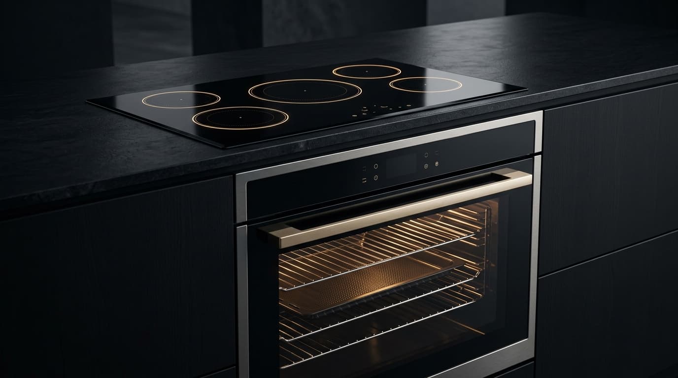
Integrated luxury convection oven and induction cooktop with illuminated touch controls
Hob
Other Brands Sharing Code E0:BoschE0LGE0WhirlpoolE0ElectroluxE0AEGE0BekoE0HaierE0ZanussiE0BrandtE0Arthur MartinE0

Symptom / Description

FAULT

Faure FIE / Induction Duo / Vitroceramic Cooktop: Electronic sub-bus communication error E0; communication between left and right induction generator modules fails.

TELEMETRY // LIVESIG: FAULT_DETECTED

Root Cause

ROOT CAUSE

On Faure (Faure FIE / Induction Duo / Vitroceramic Cooktop) models: Loose internal LIN-bus ribbon cable, oxidized molex pins, or missing 5V DC auxiliary power rail on secondary induction slave board.

CIRCUIT // SUBSYSTEMLOGIC: ROOT_ISOLATED

Repair Instructions

UNLOCKED
1Isolate hob from mains. Open casing and inspect interconnecting LIN ribbon cable. Measure continuity (< 1 Ω) and verify 5V DC on connector pin 1. Press and hold Départ/Pause and Annulation buttons for 6 seconds until all status indicators flash synchronously and clear fault memory.
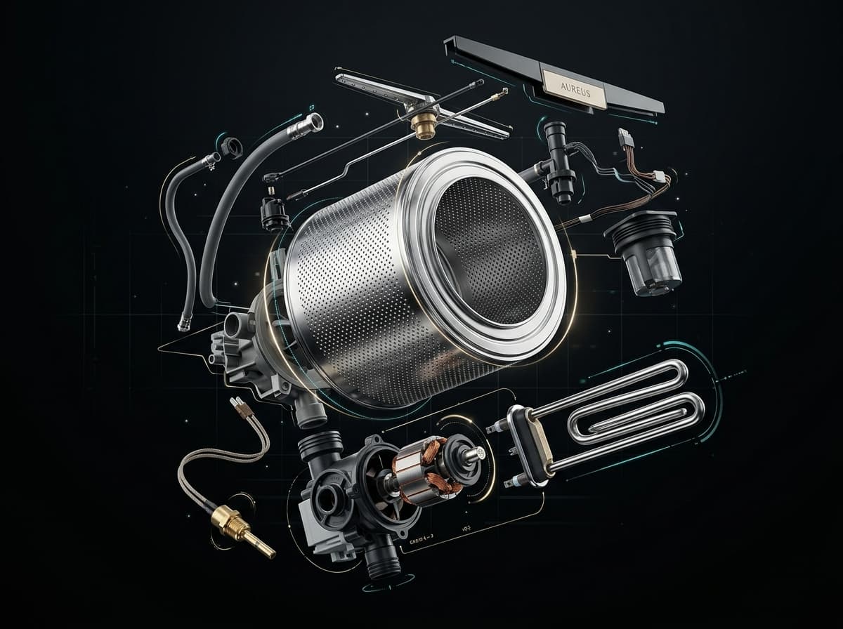
AI diagnostic workshop engine analyzing appliance circuit schematics and error telemetry in real time
AI WORKSHOP PROTOCOL ENGINE
Direct extraction from OEM factory manuals & wiring schematics

Field Actions

DISPATCH
Need Help? Call a Certified TechnicianWorldwide Faure Parts Finder
Electrical & Safety Protocol

Always disconnect appliance from 230V/400V mains before opening panels. Use CAT III multimeter for circuit testing.
CALIBRATED BENCH PROTOCOL // CAT III 600V

Workshop Verification & Safety Checklist

WORKSHOP VERIFICATION PROTOCOLElectronic Control Board (PCB) & Bus CommunicationsHob / Cooktop
2. Multimeter & Electrical Bench Tests (Ω)
MODE: OHMMETER (Ω)AUTO-RANGE
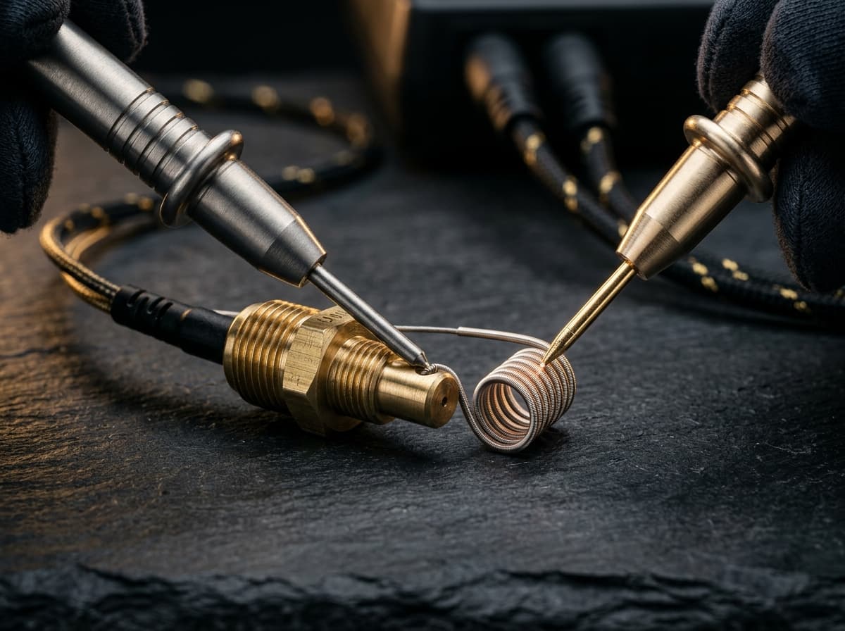
Precision digital multimeter probes measuring electrical resistance in Ohms on an appliance control board
CALIBRATED METROLOGY RESISTANCE BENCH (CAT III)
Nominal Resistance (Ω)
Low-voltage rails: +5.0V DC (Logic), +12.0V DC (Relays), +3.3V DC (MCU). Relay coils: 200Ω–450Ω.NOMINAL
0 Ω (SHORT)CALIBRATED BAND∞ OL (OPEN)
▲ NOMINAL OPERATING WINDOW
Target Component:PCB Power Supply Rails & DC Bus Filter Capacitors
Test Pins & Connections
PROBE (+)
PROBE (-)
Across SMPS output electrolytic capacitors on low-voltage side (test bench verification)
Tolerance & Diagnostic CriteriaDC rail ripple must remain <50mV. Direct continuity (0Ω) across DC bus rails indicates dead short.
1. Pre-Intervention Electrical Safety Protocols
  • !High-Voltage Safety Protocol: Disconnect 230V power before unplugging edge connectors or removing PCB.
  • !High Voltage DC Warning: Wait at least 5 minutes for SMPS and inverter filter capacitors (up to 380V DC) to discharge safely.
  • !Electrostatic Discharge (ESD): Ground yourself to the metal chassis or wear an antistatic wrist strap before touching circuit tracks.
3. Preliminary Mechanical & Visual Checks
  • Inspect PCB tracks with a magnifying glass for blown triacs, darkened copper tracks, or cold solder joints on power relays.
  • Check electrolytic capacitors for bulging tops or leaked electrolyte residue around pins.
  • Verify edge connector locking clips are intact and pins are free of vibration fretting corrosion.
Perform these diagnostic steps before triggering AI Deep Search or replacing boards.Certified Workshop Routine

Frequently Asked Questions: Faure E0

FAQ TREE
What does error code E0 mean on a Faure appliance?

Faure error code E0 indicates: Faure FIE / Induction Duo / Vitroceramic Cooktop: Electronic sub-bus communication error E0; communication between left and right induction generator modules fails..

What is the root cause of Faure error code E0?

The primary root cause for Faure code E0 is: On Faure (Faure FIE / Induction Duo / Vitroceramic Cooktop) models: Loose internal LIN-bus ribbon cable, oxidized molex pins, or missing 5V DC auxiliary power rail on secondary induction slave board..

How do I fix or resolve Faure error code E0?

To resolve error code E0: Isolate hob from mains. Open casing and inspect interconnecting LIN ribbon cable. Measure continuity (< 1 Ω) and verify 5V DC on connector pin 1. Press and hold Départ/Pause and Annulation buttons for 6 seconds until all status indicators flash synchronously and clear fault memory.

Is it safe to clear Faure error code E0 by resetting power?

Resetting power (unplugging for 5–10 minutes) clears temporary memory errors. However, if Faure code E0 persists, the physical component causing On Faure (Faure FIE / Induction Duo / Vitroceramic Cooktop) models: Loose internal LIN-bus ribbon cable, oxidized molex pins, or missing 5V DC auxiliary power rail on secondary induction slave board. must be inspected or replaced.

How do I test electrical resistance for Faure code E0 using a multimeter?

Set a digital multimeter to ohms (Ω). Disconnect power and test PCB Power Supply Rails & DC Bus Filter Capacitors across Across SMPS output electrolytic capacitors on low-voltage side (test bench verification). Expected nominal reading is Low-voltage rails: +5.0V DC (Logic), +12.0V DC (Relays), +3.3V DC (MCU). Relay coils: 200Ω–450Ω.. Tolerance: DC rail ripple must remain <50mV. Direct continuity (0Ω) across DC bus rails indicates dead short..

What safety protocol must be followed before servicing Faure code E0?

Standard electrical safety protocol: 1. Disconnect 230V mains power before opening panels. 2. Verify zero voltage at test points. 3. Allow hot water or heating elements to cool below 30°C before handling.

Community Verification

COMMUNITY

Did this solution resolve the issue?

SEMANTIC KNOWLEDGE GRAPH // FAURE

Related Faure Hob / Cooktop Error Codes

Diagnostic Link Mesh14 OEM Cross-References

Cross-referenced diagnostic codes for technicians inspecting similar component subsystems.

E1Water Level Pressure Switch & Air Dome
Faure FIE / Induction Duo / Vitroceramic Cooktop: Touch control surface blocked E1; continuo...
Inspect Protocol
E2NTC Temperature Sensor & Thermistor
Faure FIE / Induction Duo / Vitroceramic Cooktop: Induction coil overheating alarm E2; induc...
Inspect Protocol
E3General System & Mechanical Integration
Faure FIE / Induction Duo / Vitroceramic Cooktop: Mains over-voltage detected E3; supply lin...
Inspect Protocol
E4General System & Mechanical Integration
Faure FIE / Induction Duo / Vitroceramic Cooktop: Mains under-voltage detected E4; electrica...
Inspect Protocol
E5NTC Temperature Sensor & Thermistor
Faure FIE / Induction Duo / Vitroceramic Cooktop: Induction power module heatsink over-tempe...
Inspect Protocol
E6Drive Motor, Inverter & Tachometer Sensor
Faure FIE / Induction Duo / Vitroceramic Cooktop: Induction power inverter IGBT short circui...
Inspect Protocol
E7Drive Motor, Inverter & Tachometer Sensor
Faure FIE / Induction Duo / Vitroceramic Cooktop: Hob cooling fan motor fault E7; internal 1...
Inspect Protocol
E8Electronic Control Board (PCB) & Bus Communications
Faure FIE / Induction Duo / Vitroceramic Cooktop: Power supply line communication missing E8...
Inspect Protocol
E9Door Lock Mechanism & Safety Interlock
Faure FIE / Induction Duo / Vitroceramic Cooktop: Touch control configuration error E9; inte...
Inspect Protocol
EANTC Temperature Sensor & Thermistor
Faure FIE / Induction Duo / Vitroceramic Cooktop: Induction coil temperature sensor circuit ...
Inspect Protocol
FDrive Motor, Inverter & Tachometer Sensor
Faure FIE / Induction Duo / Vitroceramic Cooktop: Pan detection symbol F flashing; cooking z...
Inspect Protocol
F1Refrigeration Compressor, Defrost Heater & PTC Relay
Faure FRA / FRB Series / Defrost Control Fridge-Freezer: Fresh food compartment air sensor f...
Inspect Protocol
F2Refrigeration Compressor, Defrost Heater & PTC Relay
Faure FRA / FRB Series / Defrost Control Fridge-Freezer: Evaporator coil sensor failure F2; ...
Inspect Protocol
F3Refrigeration Compressor, Defrost Heater & PTC Relay
Faure FRA / FRB Series / Defrost Control Fridge-Freezer: Ambient room temperature sensor err...
Inspect Protocol
CodesErreur.com

Premium appliance diagnostics & repair database.
Powered by AI to help certified technicians worldwide.

Trusted by professionals in CH & FR

Platform

Search DatabasePRO Diagnostic AIPRODiagnostic ToolsBrands

Workshop Tools

Brands (87)OEM ManualsFind Rating PlateParts Locator

For Technicians

SpecialistsTechnician ForumTech JobsPremium

Corporate

Terms of ServicePrivacy PolicyOfficial Swiss Repair Partner: Electroassistance
OPERATIONAL SAFETY SPECIFICATION

SAFETY DISCLAIMER

The technical information, diagnostic guides, error codes, and AI-generated suggestions provided on this website are intended exclusively for certified and qualified professionals. Appliance repair involves severe electrical hazards, high voltages, and mechanical risks that can result in fatal injury or severe property damage. If you are not a trained technician, do not attempt to repair any appliances. CodesErreur assumes no responsibility or liability for any damage, injury, or consequential losses resulting from the use of the information provided on this platform. You use all information entirely at your own risk.

© 2026 CodesErreur. All rights reserved.

Official Swiss Repair Partner: Electroassistance Terms of Service Privacy Policy